

Move the water before it moves the land.
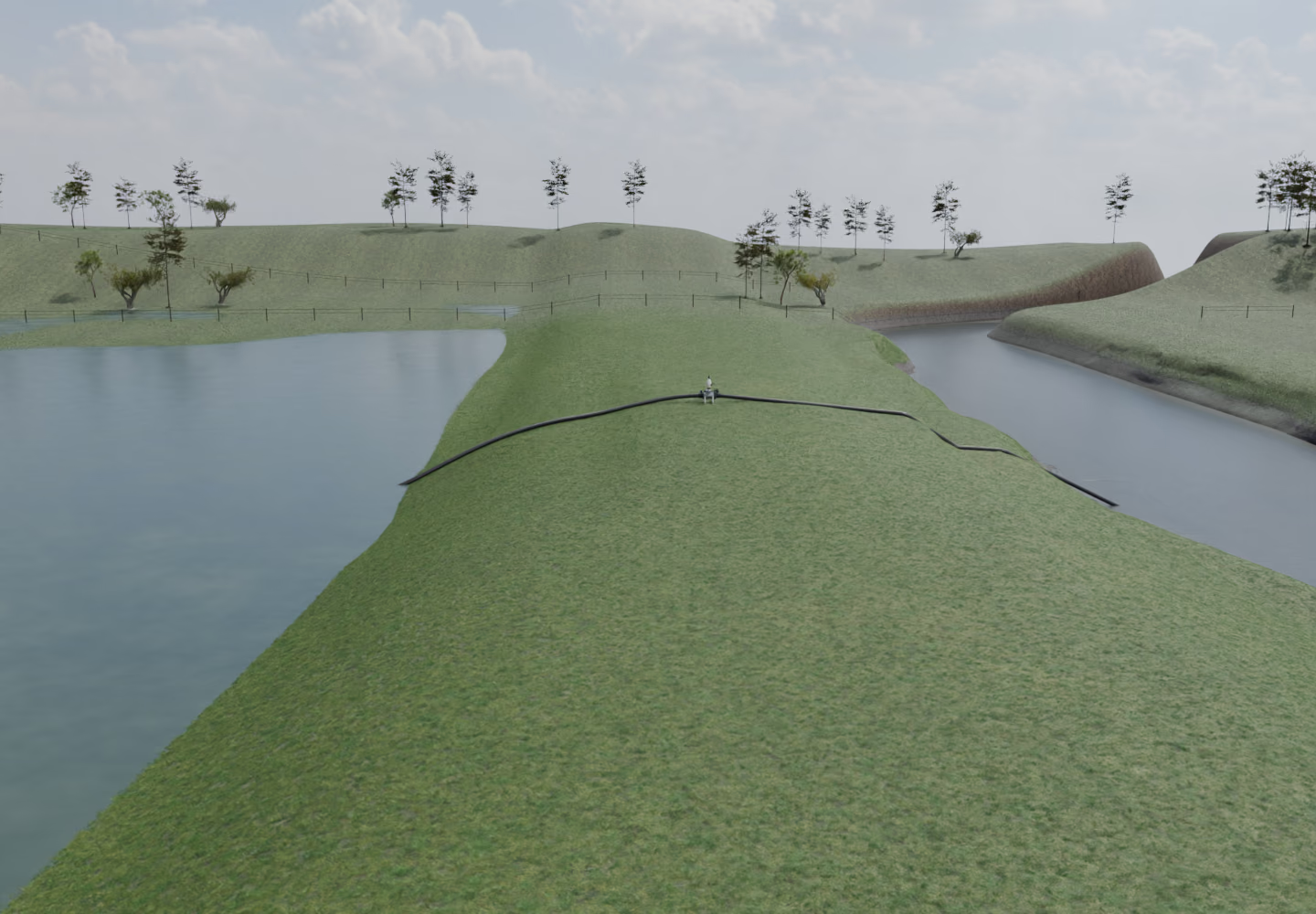
Siphonic Systems · Siphonic Transfer Unit
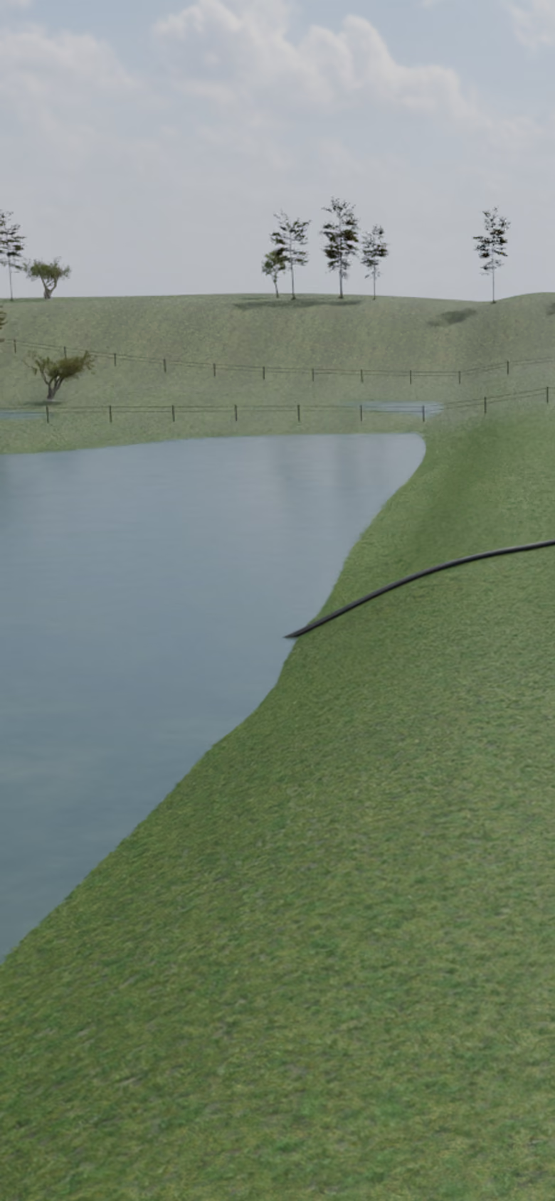
Move the water before it moves the land.
Lower water already sitting in the ground and drains — when there is somewhere lower for it to go.
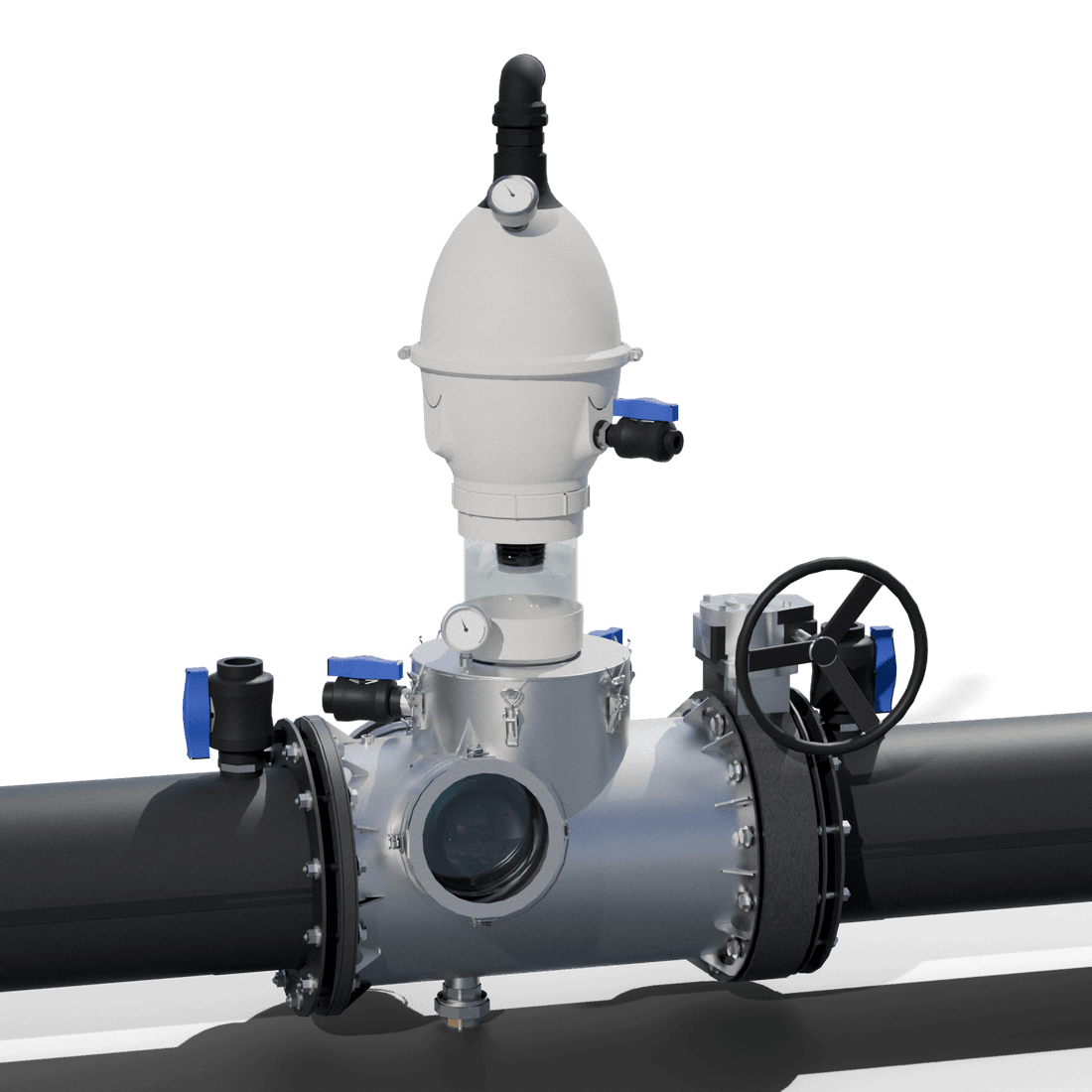
A self-priming system. No grid power.
It holds the closed pipe full from intake to outlet, and restores prime automatically after a loss.
High-volume flow through the outlet.
Once primed, the full closed pipe moves water from the higher intake water to the lower receiving water — without an inline electric lift motor.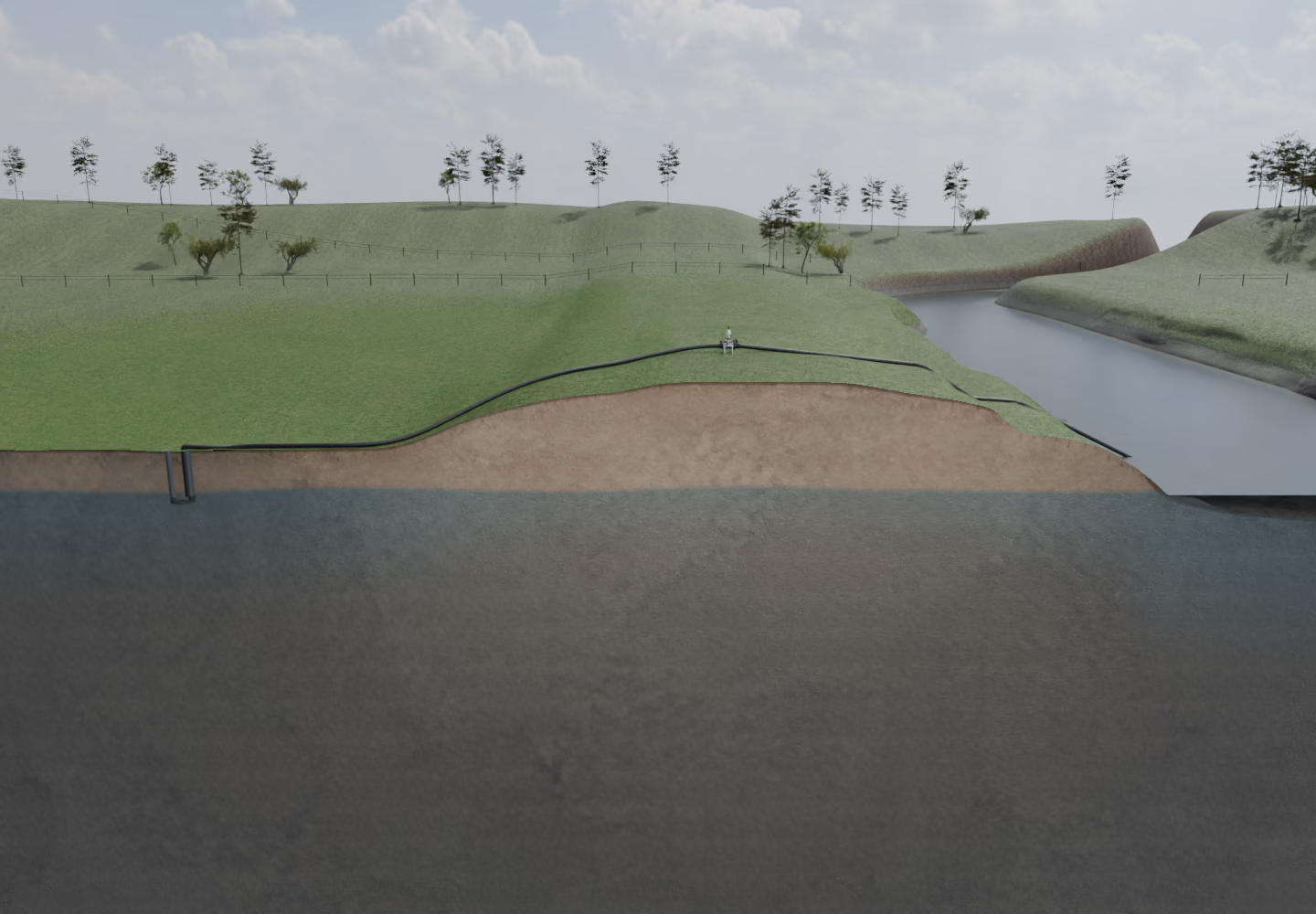
Lower the water table to free up more usable land.
Solutions that scale with your problem.
Four sizes we build. On wide animated paths the number opens at the governed 225 mm portrait and resolves at the illustrative 1800 mm+ endpoint; the compact animated path ends on the governed 1000 mm portrait. The static path names the full illustrative 150–1800 mm+ range. This is not a product list.
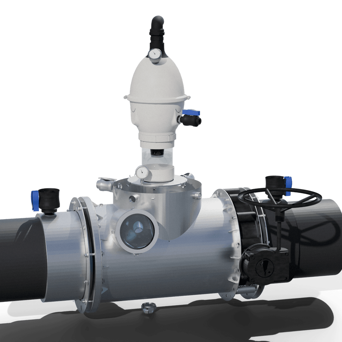
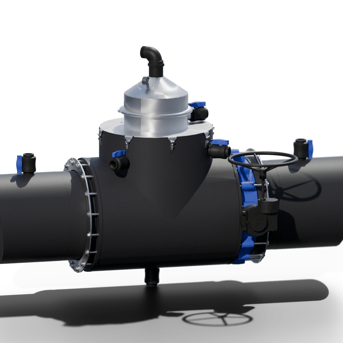
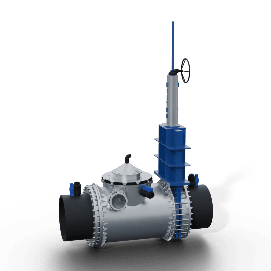
Working farms
Same unit. Two very different jobs.
At Morelands, owner/operator-reported figures describe a lower groundwater table. At Narbey, the design follows a long drain, crosses a stopbank and works within a low-tide window.
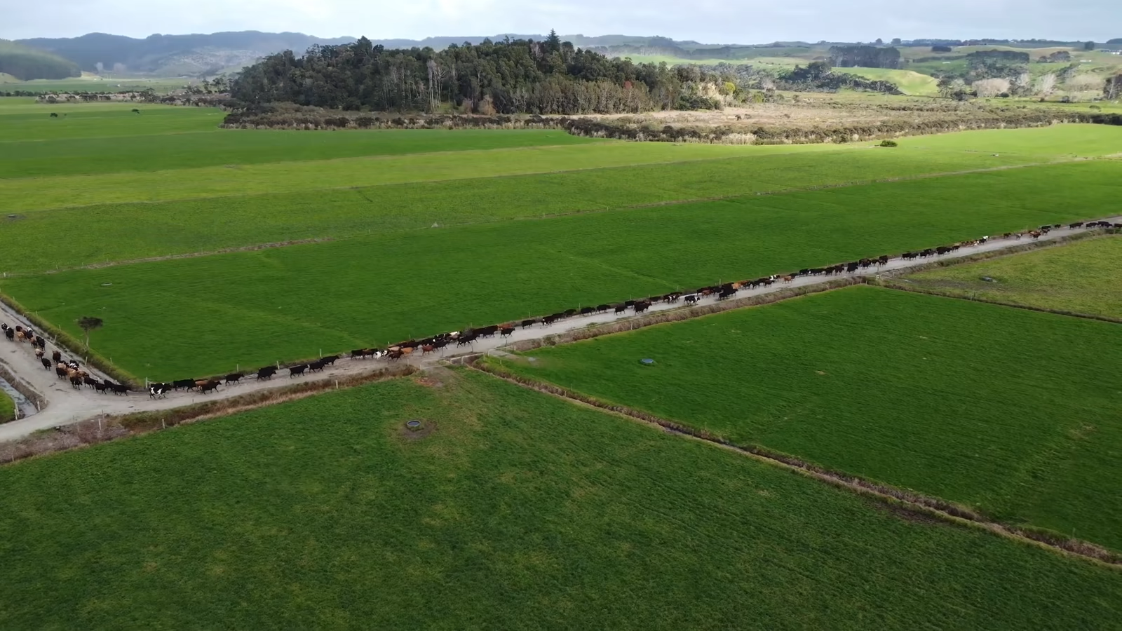
Morelands Farm
What changed when the water table came down.
Figures supplied by Morelands Farm
- 225 mmlower resting groundwater table
The resting level, measured in the ground — not a storm response.
- 400 mmlower open-drain level
Almost half a metre lower in the open drains.
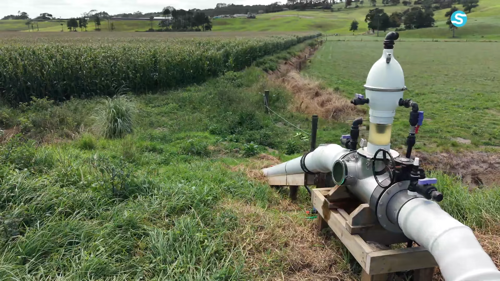
Narbey Farm
When one long drain is doing all the work.
- Long drainthe route carries water away
The video follows the existing internal drain through working ground.
- Stopbankhigher ground blocks the fall
Reclaimed land sits behind the river stopbank.
- Low tidethe receiving window moves
The design uses the river’s lower level while the tide allows it.
Preliminary site screen
See the numbers for yourself.
Enter the difference between your inlet and outlet water levels, then the approximate route. You will see the indicative screen here before we ask for any details.
Your site, drawn live
Site screening preview
What your site can move
Indicative screening flow: 47.4 L/s. Water-level difference: 2.0 metres.
Worked example
Water-level difference: 2.0 m
Indicative screening flow
47.4L/s
- Volume each hour
- 171 m³/hour
- Velocity in the pipe
- 1.51 m/s
Steady-state screening estimate for a fully primed closed pipe — not a design figure.